Previously, I’ve written about FlowSharpCode and Visual Assisted Programming / Organizational Representation (V.A.P.O.R.) Here’s a simple example of what I mean by this concept.
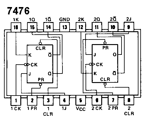
My first technology passion was actually hardware, but it was expensive (a 7476 flip flop in the 70’s cost $4.50 from Radio Shack, if I remember correctly.) So I started goofing around with software — BASIC on a PDP/11, HP calculators, BASIC on a Commodore PET, etc.
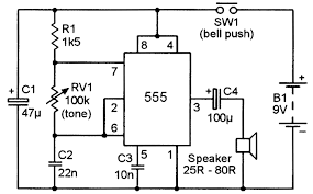
But software was always missing something for me – a visual way of describing what the software does. You see, software and hardware are very similar — they are both essentially a circuit. With hardware, the lines describe the paths of electrons (signals) and the components describe how those signals are manipulated, (their voltages and current) like in this simple circuit that produces a tone you can vary using a 555 timer chip, a speaker, and some discrete components:

(By the way, the history of the 555 timer is quite amazing.) “Camenzind spent nearly a year testing breadboard prototypes, drawing the circuit components on paper, and cutting sheets of Rubylitha masking film. “It was all done by hand, no computer,” he says. His final design had 23 transistors, 16 resistors, and 2 diodes.”
If we want to write a simple WinForm C# app to do the same thing (more or less):
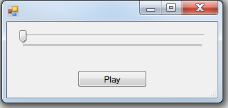
we need about 142 lines of code, which you can view on this Gist.
The Play button acts like B1 in the schematic, the trackbar is the variable resistor in RV1, and the code implements the 555 timer (generates a sine wave in this case) and speaker is actually a call to System.Media.SoundPlayer
So What’s the Problem?
Someone was said to me that they would never use an editor that didn’t have outlining capability. And you can sort of see why — even 142 lines of code is a lot to look at to glean what is going. Outlining helps:
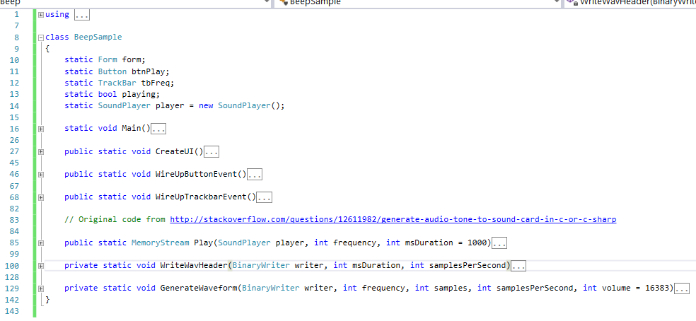
because at least it shows you what the top level methods are, so you can see what the programmer had in mind for overall structure.
If the programmer wrote the code with a sufficient fine level of granularity. That’s a big “if.” In fact, I refactored my original code (which was originally just Main and Play, so that there was something more to show here in the outline.
A good IDE also provides some useful information – here is what Visual Studio tells you about the file:
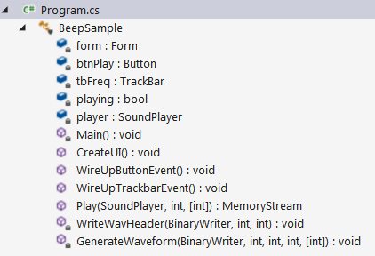
In both cases, what is lost is what was expressed so nicely in the hardware schematic:
the flow of signal! A list of classes, fields, properties, and methods is like getting a bag of wires, chips, and discrete components:

you still have no idea of how the program wires it all up! To figure that out, you have to read the code and create, for yourself, a mental map (or maybe even some pen & paper flowcharting) of what the code is doing. For the sound player, that’s trivial. For thousands (or hundreds of thousands or millions of lines) of code, that is anything but trivial.
But We’ve Been Here, Done That
Or have we? It’s ironic to me that hardware engineers are always using visual tools (software nowadays) to design, implement, and simulate their hardware, yet we have nothing like that for software. Sure, there’s been numerous attempts, and of course we have various tools that create diagrams for us or even let us work in a diagramming mode. Some of these tools will generate code stubs, some will reverse engineer code into diagram (the most sophisticated of which can actually parse your code.)
A few visual tools that have been tried, some with limited success, are:
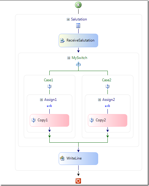
UML
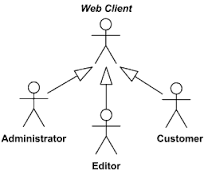
BPEL and WWF
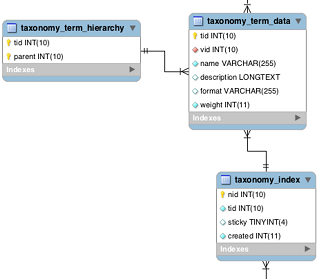
Schema Diagramming
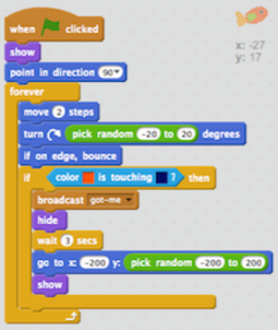
Lego-like Programming (like Scratch)
Do These Tools Work?
For what they’re designed to do, yes, but I find these tools do very little to help me express visually the day-to-day work of writing code. They are either too high level, too abstract, or too low level, too childish, or don’t work with the languages that I use, and, most importantly, limit me in how I want to express concepts, at the granularity that I think is appropriate.
V.A.P.O.R – Visual Assisted Programming / Organic Representation
You may notice I changed that “O” to Organic (it used to be Organizational.)
This is one way to express what the tone player “circuit” look like using FlowSharpCode (the thing that implements V.A.P.O.R):
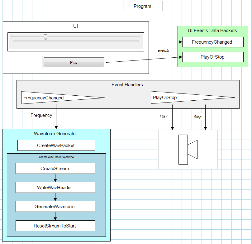
This should give you a moment of pause.
Notice:
- Yes, this is a working, running, application.
- The UI is on the same surface as the implementing code.
- The surface is visual, annotated representation of the program.
- A simple workflow is demonstrated, which helps to visualize the individual steps of a particular process.
- Arbitrary shapes and groups can be used for code fragments.
Where’s the Code?
That’s the beauty if it. The code is embedded in each shape. The shape can be anything–in fact, the speaker is actually a grouped rectangle and a triangle with appropriate z-ordering. The code-behind is in the group box containing those two shapes!
IC’s
We can even package code into re-usable “integrated circuits”, implemented either as separate assemblies (dll’s) or simply by grouping them into logical and re-usable compositions:
- The Waveform Generator group is like the 555 timer.
- The speaker is, well, a speaker.
- The Play button is like the button in the schematic.
- The TrackBar control is like the variable resistor that changes the frequency.
If I want to re-use an IC (or even just a code fragment), I just copy and paste the desired shapes to my own application surface, and I get the shapes, the annotations, and the code-behind.
Now, granted, there’s three “IC’s” to make this all work that I haven’t shown in the picture above, consisting of:
- A bootstrapper to handle UI events (and internal events, but there aren’t any in this application.)
- A simple server that provides the communication channel to interface between the UI events and the application. Why? Because the UI events are actually generated from services running in the FlowSharpCode application, and we need to inform the SoundPlayer application of those events.
- A mechanism for updating the UI (which is hosted in FlowSharpCode) when state changes, in this case, Play and Stop.
More on all this later!
Is this concept limited to C# code?
Certainly not. While I’m using C# for this demonstration and the SharpDevelop code editor, the code editor, compiler, etc, are services that are plugged in to FlowSharpCode. Other services, supporting Java, Javascript, Node, Ruby, Python, along with syntax highlighting editors, etc., can be plugged in to FlowSharpCode as well. In fact, one of the goals is to write FlowSharpCode as a web application, where your code, in whatever language you like, is built on a server, and you’re actually building web apps.
Can Coding be More Like Circuit Layout?
I certainly think so, and besides this simple demonstration, I’ve used this same process for writing an implementation of my favorite “prove the technology” game, Hunt The Wumpus. I’ll be writing more about that soon!

Great article, great concept. The V.A.P.O.R.ware article has just been placed in my very small “to Read” list, only because it is now bedtime, and reading it might keep me up all night.